Motor and Generator Maintenance Services
Motor Repair & Rewinding Services
Electric motors are among the highest reliability incident reports for many companies. This leads to a continual cycle of costly electric motor repair, inconsistent quality and unplanned downtime factors that can hurt your bottom line. We not only repair and refurbish your motor but to provide root cause failure analysis on why it has failed. We consistently provide electric motor repairs and refurbishments that are better than new motors!
Our comprehensive Electric Motor Service, repairs motors, when you need them, performed to state-of-the art standards. Shop and Field Service support capabilities include 24 hour service, 7 days a week.
Our AC Motor Repair services include:
Reconditioning
Repair, reconditioning, and adjustment of the Electric Motor• Stator components’ parts are thoroughly cleaned and baked dry. Replacement of Bearings, Seals and any auxillary componants, as required.
Rewinding
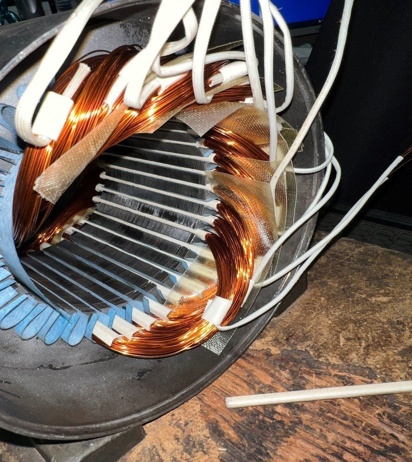
Complete refurbishing of the Electric Motor• Stator componants are rewound with inverter rated magnet wire using NEMA Class “H” insulation system. Replacement of Bearings, Seals and any auxillary componants, as required.
Modifications
We offer application design and assistance, plus the capabilities of modification of New Electric Motors and Generators to meet your specific requirements.
Testing
AC Motors are tested using non-destructive winding analysis and testing and test run for proper electrical and mechanical operation. Voltage, Current, Bearing temperature, and Vibration are closely monitored and documented.
We know Motors! Contact us for a Motor Repair Quote, a Replacement Motor, or Predictive Maintenance Plans.
Repair Service for all types of AC Motors of the following designs:
- Induction Motors
- Synchronous Motors
- Inverter Duty Motors
- Hoist/Crane Motors
- Printing Press Motors
- Explosion-Proof Motors
- Fan & Blower Motors
- Conveyor Motors
- Washdown Duty Motors
- Shaker Duty Motors
- Wound-Rotor (Slip-Ring) Motors
- Commutator Motors
- Cooling Tower Motors
- Spindle Motors
- Specialty Motors
- Vertical Hollow Shaft Pump Motors
- Submersible Pump Motors
- Eddy Current Clutches
- Chemical Processing Motors
- Gearmotors
AC Electric Motors are used in applications from a small, special purpose apparatus to those driving large-scale industrial machinery. The most common type of AC Electric Motor used in Industry is the Asynchronous Motor or (as more commonly referred to) Induction Motor.
The Induction motor is an AC Electric Motor in which the electric current in the rotor needed to produce torque is obtained by electromagnetic induction from the magnetic field of the stator winding. An induction motor can therefore be made without electrical connections to the rotor as are found in Universal, DC Motors and Synchronous Motors. An induction motor’s rotor can be either wound type or squirrel-cage type. Three-phase squirrel-cage induction motors are widely used in industrial drives because they are rugged, reliable and economical. Induction motors are increasingly being used with Variable-Frequency Drives (VFDs) in variable-speed service. EMX Motor Repair Shop has the expertise to design a VFD package which can offer especially important energy savings opportunities for existing and prospective induction motors. Typical uses include constant and variable- torque Centrifugal Fan, Pump and Compressor load applications. EMX Motor Repair Shop offers the capability, reliability, experience, and customer service needed to completely refurbish motors, as well as provide expert Motor & Drive solutions.
Every aspect of our AC Motor Repair shop, from electric motor rewinding to electric motor part repair, is performed under the stringent quality standards. As a reflection of our uncompromising commitment to customer satisfaction, all of EMX Electric Motors Service work is 100% guaranteed.
Incoming Inspection
EMX Motor Repair Shop performs a thorough appraisal of the motor’s condition, as received, to determine what specific repairs are needed as well as to find unsuspected trouble, perhaps unrelated to the obvious defect. Our technicians diagnose cause and effect to help prevent a recurrence. The motor may have been sent to our Repair Facility with limited external evidence as to the nature and location of trouble. What seems wrong may be correctable in several ways. Our appraisal will include a complete review of the following conditions of each part of the motor: General cleanliness, Cracked or broken welds or castings, Missing hardware, Wear or rub marks, including fretting, discoloration, charring, or other evidence of overheating , Looseness at mating fits, Corrosion, moisture, or oil inside the machine. Digital Photographs of any abnormal conditions found are part of the appraisal process and inspection report. Our AC Motor Repair includes dissassembly, detailed inspections, and measurements to identify electrical and mechanical damage.
Incoming Tests
Prior to an incoming run test, we perform the following and record information where appropriate: Motor will be mechanically inspected to determine if shaft turns freely, Verify that bearings are lubricated, Insulation resistance tests are performed. As well as , the continuity of stator windings, condition and installation of brushes, if applicable, Single-phase, low-voltage test (approximately 10-20% of rated voltage) on AC squirrel-cage rotor to find defective rotor bars, Polarization index (where appropriate). Surge test (where appropriate). If conditions permit, the motor will be run at reduced voltage initially (25-50% of rated voltage). If the test is successful, Results are recorded, and then the motor will be run at full rated voltage, if possible. The intent of the “As Received”, no load, run test is to get the motor operating safely up to top speed for electrical characteristics, bearing temperature, and vibration checks prior to dissassembly. If the “As Received” motor conditions permit, the motor shall be run to 100% speed for these tests.
Disassembly & Inspection
Before any disassembly is begun, parts will be marked (i.e., brackets, frame, covers, and brush holders). Brackets and bearings will be identified as pairs. Check and record rotor air gap. Frame-mounted devices will be identified and recorded. Electrical wiring is recorded, sketched, and marked before disconnecting (for external connection).
The condition of the windings and the extent of repairs are determined by inspection and, as necessary, by testing. Stator Windings are observed for the following: Slot wedges (“top sticks”) that are loose, damaged, or have shifted in position. Ties, lashings, or blocking that are loose or broken. Dirt, oil, or moisture deposited on coil surfaces. Coil damage – Besides obvious burning, tracking, or charring, we look for loose or cracked tape, coils that have moved within the slot, deposits of dirt or chemicals, and insulation pitted or worn away by airborne abrasive particles. Winding integrity is determined using non-destructive winding analysis and testing. Bars and end rings for amortisseur and squirrel cage windings are examined for evidence of defects. Additional Testing may be required.
The Rotor is the second major electrical component to be appraised. Cleanliness, laminations, vent spacers, slot tooth condition, and rub marks are checked as in the stator. Rotor laminations are checked for “coning” (separation of laminations, causing the length of the rotor to be greater at the outer diameter than it is at the shaft). Electric Motor components & parts are thoroughly cleaned. Steam cleaning is the preferred method. Shafts will be checked for wear, cracks, scoring and straightness. (NEMA MG 1-2003 Rev.1-2004, Section 1, Part 4 Par. 4.11); cracks, corrosion; scoring or galling. Shaft extensions should be smooth, polished and concentric with the shaft center. Shaft extension dimensions and permissible runout will be checked and Diameter Tolerances for NEMA/IEC frame size machines compared. Keyseat/ Keyway Width Tolerances checked against NEMA/IEC Frame Size machines Tables. Keyseats will be true and accommodate keys to tap fit. If the shaft requires repair, worn surfaces can be restored within our Machine Shop to factory specification. Ball or Roller Bearings (Antifriction bearings) are comprehensively inspected for condition of lubricant; dirt, rust, or moisture; fretting corrosion; thermal discoloration; pitting or spalling of balls, rollers, or races; broken or missing retainers. Sleeve Bearings are checked to be uniform in diameter, of proper fit in the housing, smooth internally and suitably grooved for adequate distribution of lubricant. Bearing Housings and Shaft bearing fits are measured and compared to manufacturer’s specifications. Any fits that are not within tolerance are restored to original factory specification. Seals & Seal clearance are set to original equipment manufacturer’s specifications if available. Oils used will compatible with the customer’s lubricant. Frame and Bearing Housings will be examined for defects; Corrosion; structural weld integrity; blocked drains, breathers, or ventilating air passages; paralleling of feet. Cracks and breaks are repaired and fits restored to manufacturer’s specifications.
Electric Motor Accessories, such as, capacitors are tested for rated capacitance, and subjected to a high-potential test. Capacitors are replaced if damaged. Short circuit devices, centrifugal mechanisms, switches, and starting relays are verified for electrical and mechanical operation at correct speed and voltage. Space heaters are tested for rated current or power and subjected to a high-potential test. They will be replaced if damaged. Bearing temperature sensors or protectors will be identical with or equivalent to the original devices in electrical and thermal characteristics.
Balancing
EMX’ Shop Balancing Systems are designed to perform measurements of vibrations and calculations in horizontal shop balancing machines and in the field. The application measures the running speed (1X) filtered vibration amplitude and relative phase with a reference mark in the rotor to allow full balancing correction. Dynamic Balancing results are to be performed to the level specified by the customer. In the absence of a requested level, dynamic balancing to balance quality grade G2.5 (ISO 1940/1) should enable the machine to meet final vibration limits. Note: Balance Weights are to be located so that they do not interfere with other machine components.
Recondition of Stator
Stator components’ parts are thoroughly cleaned by Steam cleaning, as the preferred method. Cleaning will continue until all vent slots are free of any obstruction which may interfere with proper cooling of the motor. Insertion of any metal object into ventilation passages of a stator is unacceptable under any circumstances. Prior to an re-insulating application, the windings will be preheated to 110°F to 130°F to remove air and moisture. Oven temperature will not exceed 290°F during the drying cycle for Class “F” or “H” insulation. Oven temperature will not exceed 250°F for Class “A” or “B” insulation. A Final megger reading must exceed 10 megohms at room temperature., at which time either the spray or flow method or the “Dip and Bake” method can be used. A reading below 10 megohms requires communications with the User and determination will be made as to rewind the Stator verses the cost of motor replacement.
In the event that Rewinding of Stator is the better choice in the repair of the Electric Motor, the winding will be re-manufactured using an inverter rated magnet wire and the insulation exclusively classified as follows: NEMA Class “H” An insulation system (180°C temperature limit including a 40°C ambient or 140°C rise) that by experience or accepted test can be shown to have suitable thermal endurance when operating at the limiting Class H temperature specified in the temperature rise standard for the machine under consideration. EMX Motor Repair Shop can redesign motors using computer aided motor redesign and assures that all Winding data is thoroughly reviewed for accuracy. The winding should maintain the same electrical characteristics as the original unless redesigned by agreement with, or at the instruction of, the customer. The entire Insulation System, materials, and methods of application should be equal to or better than that used by the original machine manufacturer. All components of the insulation system will be compatible with each other with respect to electrical, mechanical, and thermal characteristics. RTDs or thermocouples are placed within the windings if they were part of the original design or requested to be added by the User. AC Motors are rebuilt using the highest-quality wire, insulation, and varnish materials for long-lasting repairs in the most severe industrial environments.
Assembly
All mechanical repairs on shafts, bearing journals, end bells, and other equipment are handled in-house by experienced machinists. All Electric Motor assemblies are made in accordance with good machine shop practices. If the shaft requires replacement, a new shaft will be made of A.I.S.I. 4140 Steel HRHT (Hot Rolled Heat Treated). Under special cases, shaft material will be replaced with 316 stainless or User approved material. Motors will be assembled in a manner that will ensure proper fit and alignment. Ball and Roller Bearings are fitted to shafts by heat-expanding the inner bearing race in accordance with the bearing manufacturer’s recommendations, however, not to exceed 250°F, using an oil-bath heater or an induction heater. Check and record air gap. All bolts, nuts, etc., will be replaced as required with SAE grade 5 or better and torqued to Industry standards. On metric fasteners we will use a grade 8.8 or better. All assembled components will be checked to ensure secure fits. All covers on openings in the frames or housings will be fastened in a closed position.
Final Run Test
Every AC Motor repaired is tested for proper electrical and mechanical operation. Voltage, Current, Bearing temperature, and Vibration are closely monitored and documented. AC Motors are Run tested at minimum of 60 minutes duration at the rated voltage and until the temperature of the bearings have stabilized (+/- 1°C over 15 minutes). A maximum temperature of 150°F on babbitt bearings shall not be exceeded (unless bearing manufacturer specifies otherwise). On antifriction bearings and on motors with a cooling fan, the bearing housing temperature should not exceed 30°F above ambient temperature for oil lubrication, and 50°F above ambient for grease lubrication. On motors without external cooling fans, the bearing housing temperature should not exceed 50°F above ambient. At no time should the temperature exceed the drop test temperature of the lubricant. On squirrel-cage motors, we check the current on all connections and check speed of the motor. The current on each phase should be within 10% deviation between any two other phases. On wound rotor motors, we apply full primary voltage to stator and with rotor circuit open for a non-rotational test and measure rotor open circuit voltage and stator current. A non-load test run will be made on all motors to ensure that all electrical readings do not exceed the Name Plate Data ratings. A written record of all tests and inspection results will be furnished to the user upon completion of repairs.
Completed apparatus will be externally cleaned and painted to specification. Shaft extensions are treated to prevent corrosion. Packaging and Transportation: After completion of the repair and testing, the machine will be packed in a manner suitable for the form of transport to be used. Packing and transport will be as arranged with the customer. Shaft is Blocked to prevent movement, depending on the type of machine, mode of transport and the distance to be traveled. Where blocking is used, it will be clearly identified. Oil-lubricated machines will be shipped without oil, and the need for lubricant clearly identified.
EMX Benefits
- Complete Motor Inspection and Cleaning
- Provide complete failure and documentation to determine the cause of Motor Failure
- Comprehensive Bearing Inspection and new Bearing Installation
- Digital pictures available for Inspection
- Commissioning of your Equipment
- Non-destructive winding analysis and testing
- All Rewinds are made using Class “H” Insulation & Inverter Duty Wire
- Utilize the best available technology in the repair of your Motor.
- Treat your Motor problems with concern.
AC & DC Generator Repair, Inspection, and Maintenance services
When it comes to long-term reliable service, industrial generators have no rival. The near constant ability to stay active despite power failures and major systematic errors is impressive. Manufacturing plants inherently rely on the wide functionality of these generators to keep their business lively and productive. We not only repair and refurbish your Generator but to provide root cause failure analysis on why it has failed, and provide ongoing maintenance services.
Our comprehensive Generator Service, makes repairs, when you need them, performed to state-of-the art standards. Shop and Field Service support capabilities include 24 hour service, 7 days a week.
Our Generator Repair services include:
Reconditioning
Repair, reconditioning, and adjustment of the Generator• Stator components’ parts are thoroughly cleaned and baked dry. Replacement of Bearings, Seals and any auxillary componants, as required.
Rewinding
Complete refurbishing of the Generator• Stator componants are rewound with inverter rated magnet wire using NEMA Class “H” insulation system. Replacement of Bearings, Seals and any auxillary componants, as required.
Modifications
We offer application design and assistance, plus the capabilities of modification of New Generators to meet your specific requirements.
Testing
Generators are tested using non-destructive winding analysis and testing and test run for proper electrical and mechanical operation. Output Voltage, Speed, Bearing temperature, and Vibration are closely monitored and documented.
We know Generators! Contact us for a Generator Repair Quote, a Replacement Generator, or Predictive Maintenance Plans.
Repair Service for all types of Generators in the following categories:
- (AC) Alternating Current
- (DC) Direct Current
- Deisel
- Natural Gas
- Liquid Propane
- (MG) Motor-Generator Sets
- Portable
An electric generator is a machine that uses mechanical energy to produce electrical charges and move them through an electric current. Its engine creates mechanical energy which is pushed through an electrical conductor in a magnetic field, creating electric charges and generating electric current. A generator has various components, including an engine, an alternator, a fuel system, a voltage regulator, cooling and exhaust systems, a lubrication system, a battery charger, a control panel, and a frame or main structure.
Motor Testing and Analysis
Incoming Inspection
EMX Motor Repair Shop performs a thorough appraisal of the Generator’s condition, as received, to determine what specific repairs are needed as well as to find unsuspected trouble, perhaps unrelated to the obvious defect. Our Mechanic’s diagnose cause and effect to help prevent a recurrence. The generator may have been sent to our Repair Facility with limited external evidence as to the nature and location of trouble. What seems wrong may be correctable in several ways. Our appraisal will include a complete review of the following conditions of each part of the Generator: General cleanliness, Cracked or broken welds or castings, Missing hardware, Wear or rub marks, including fretting, discoloration, charring, or other evidence of overheating , Looseness at mating fits, Corrosion, moisture, or oil inside the machine. Digital Photographs of any abnormal conditions found are part of the appraisal process and inspection report. Our Generator Repair includes dissassembly, detailed inspections, and measurements to identify electrical and mechanical damage.
Incoming Tests
Prior to an incoming run test, we perform the following and record information where appropriate: Generator will be mechanically inspected to determine if shaft turns freely, verify that bearings are lubricated, Insulation resistance tests are performed. As well as , the continuity of stator windings, condition and installation of brushes, if applicable, Polarization index (where appropriate). Surge test (where appropriate). If conditions permit, the generator will be run at reduced speed initially (25-50% of rated voltage). If the test is successful, Results are recorded, and then the generator will be run at full rated speed, if possible. The intent of the “As Received”, no load, run test is to get the generator operating safely up to top speed for electrical characteristics, bearing temperature, and vibration checks prior to dissassembly. If the “As Received” generator conditions permit, the generator shall be run to 100% speed for these tests.
Disassembly & Inspection
Before any disassembly is begun, parts will be marked (i.e., brackets, frame, covers, and brush holders). Brackets and bearings will be identified as pairs. Check and record rotor air gap. Frame-mounted devices will be identified and recorded. Electrical wiring is recorded, sketched, and marked before disconnecting (for external connection).
The condition of the Field & Armature windings and the extent of repairs are determined by inspection and, as necessary, by testing. Coil windings are observed for the following: Slot Wedges (“top sticks”) that are loose, damaged, or have shifted in position. Ties, lashings, or blocking that are loose or broken. Dirt, oil, or moisture deposited on coil surfaces. Coil damage – Besides obvious burning, tracking, or charring, look for loose or cracked tape, coils that have moved within the slot, deposits of dirt or chemicals, and insulation pitted or worn away by airborne abrasive particles. Winding integrity is determined using non-destructive winding analysis and testing. In a DC Machine, the Commutator is machined and undercut and Armature windings are examined for evidence of defects. Additional Testing may be required.
Generator components & parts are thoroughly cleaned. Steam cleaning is the preferred method. Shafts will be checked for wear, cracks, scoring and straightness. (NEMA MG 1-2003 Rev.1-2004, Section 1, Part 4 Par. 4.11); cracks, corrosion; scoring or galling. Shaft extensions should be smooth, polished and concentric with the shaft center. Shaft extension dimensions and permissible runout will be checked and Diameter Tolerances for NEMA/IEC frame size machines compared. Keyseat/ Keyway Width Tolerances checked against NEMA/IEC Frame Size machines Tables. Keyseats will be true and accommodate keys to tap fit. If the shaft requires repair, worn surfaces can be restored within our Machine Shop to factory specification. Ball or Roller Bearings (Antifriction bearings) are comprehensively inspected for condition of lubricant; dirt, rust, or moisture; fretting corrosion; thermal discoloration; pitting or spalling of balls, rollers, or races; broken or missing retainers. Sleeve Bearings are checked to be uniform in diameter, of proper fit in the housing, smooth internally and suitably grooved for adequate distribution of lubricant. Bearing Housings and Shaft bearing fits are measured and compared to manufacturer’s specifications. Any fits that are not within tolerance are restored to original factory specification. Seals & Seal clearance are set to original equipment manufacturer’s specifications if available. Oils used will be compatible with the customer’s lubricant Frame and Bearing Housings will be examined for defects; Corrosion; structural weld integrity; blocked drains, breathers, or ventilating air passages; paralleling of feet. Cracks and breaks are repaired and fits restored to manufacturer’s specifications.
Additional Generator components, such as the alternator, fuel system, voltage regulator, cooling and exhaust systems, the lubrication system, and battery charger are inspected and tested. Space heaters are tested for rated current or power and subjected to a high-potential test. They will be replaced if damaged. Bearing temperature sensors or protectors will be identical with or equivalent to the original devices in electrical and thermal characteristics.
Balancing Armature
EMX Shop Balancing Systems are designed to perform measurements of vibrations and calculations in horizontal shop balancing machines and in the field. The application measures the running speed (1X) filtered vibration amplitude and relative phase with a reference mark in the rotor to allow full balancing correction. Dynamic Balancing results are to be performed to the level specified by the customer. In the absence of a requested level, dynamic balancing to balance quality grade G2.5 (ISO 1940/1) should enable the machine to meet final vibration limits. Note: Balance Weights are to be located so that they do not interfere with other machine components.
Recondition of Field Coils & Armature
Electrical components’ parts are thoroughly cleaned. Steam cleaning is the preferred method. Cleaning will continue until all vent slots are free of any obstruction which may interfere with proper cooling of the motor. Insertion of any metal object into ventilation passages of a Fields or Armature is unacceptable under any circumstances. Prior to an re-insulating application, the windings will be preheated to 110°F to 130°F to remove air and moisture. Oven temperature will not exceed 290°F during the drying cycle for Class “F” or “H” insulation. Oven temperature will not exceed 250°F for Class “A” or “B” insulation. A Final megger reading must exceed 1 megohms at room temperature., at which time either the spray or flow method or the “Dip and Bake” method can be used. A reading below 10 megohms requires communications with the User and determination will be made as to rewind the Fields or Armature verses the cost of motor replacement.
In the event that Rewinding of Field Coils or Armature is the better choice in the repair of the Generator, the winding will be re-manufactured using an inverter rated magnet wire and the insulation exclusively classified as follows: NEMA Class “H” An insulation system (180°C temperature limit including a 40°C ambient or 140°C rise) that by experience or accepted test can be shown to have suitable thermal endurance when operating at the limiting Class H temperature specified in the temperature rise standard for the machine under consideration. The entire Insulation System, materials, and methods of application should be equal to or better than that used by the original machine manufacturer. All components of the insulation system will be compatible with each other with respect to electrical, mechanical, and thermal characteristics. RTDs or thermocouples are placed within the windings if they were part of the original design or requested to be added by the User. Generators are rebuilt using the highest-quality wire, insulation, and varnish materials for long-lasting repairs in the most severe industrial environments.
Assembly
All mechanical repairs on shafts, bearing journals, end bells, and other equipment are handled in-house by experienced machinists. All Generator assemblies are made in accordance with good machine shop practices. If the shaft requires replacement, a new shaft will be made of A.I.S.I. 4140 Steel HRHT (Hot Rolled Heat Treated). Under special cases, shaft material will be replaced with 316 stainless or User approved material. Generator will be assembled in a manner that will ensure proper fit and alignment. Ball and Roller Bearings are fitted to shafts by heat-expanding the inner bearing race in accordance with the bearing manufacturer’s recommendations, however, not to exceed 250°F, using an oil-bath heater or an induction heater. Check and record air gap. All bolts, nuts, etc., will be replaced as required with SAE grade 5 or better and torqued to Industry standards. On metric fasteners we will use a grade 8.8 or better. All assembled components will be checked to ensure secure fits. All covers on openings in the frames or housings will be fastened in a closed position.
Final Run Test
Every Generator repaired is tested for proper electrical and mechanical operation, as long as an adequate prime mover is available . Voltage, Speed, Bearing temperature, and Vibration are closely monitored and documented. Generators are Run tested at minimum of 60 minutes duration at the rated voltage and until the temperature of the bearings have stabilized (+/- 1°C over 15 minutes). A maximum temperature of 150°F on babbitt bearings shall not be exceeded (unless bearing manufacturer specifies otherwise). On antifriction bearings and on Generators with a cooling fan, the bearing housing temperature should not exceed 30°F above ambient temperature for oil lubrication, and 50°F above ambient for grease lubrication. On units without external cooling fans, the bearing housing temperature should not exceed 50°F above ambient. At no time should the temperature exceed the drop test temperature of the lubricant. A written record of all tests and inspection results will be available to the user upon completion of repairs.
On-site Generator Repair and Maintenance services:
- Electrical repairs - Repair or replacement of contactors, regulators and timers, etc.
- Troubleshooting - Troubleshooting & repair of unexpected generator malfunctions.
- Generator Inspection & Maintenance Plans
EMX performs a comprehensive inspection of the emergency power supply system following NFPA 110 guidelines, as well as the requirements of the NEC Article 701 for Required Standby Systems and can make all needed repairs. This inspection covers all the systems of the lubricating, air, fuel, cooling, exhaust, battery, generator, generator controls and safety system, room air inlet and exhaust. Our inspectors are professional and reliable and provide you with a full equipment evaluation including condition monitoring, inspection reporting, and operational testing.
Generator Maintenance Plan Inspection
- Engine Lubrication Systems: Inspect engine for leaks; oil and filters changed
- Engine Air Cleaners: Wet type: clean and change oil yearly. Dry Type: Clean or replace filter.
- Ignition Systems: Check magneto and replace spark plugs as needed.
- Governor: Check and set speed, sensitivity and oil level.
- Engine Cooling System: Check general condition, anti-freeze, coolant level, belts and hoses.
- Engine Electric System: Test battery and clean battery posts and cables.
- Engine Fuel System: Inspect for leaks. Check all connections and fuel lines.
- Engine Exhaust System: Check for leaks and corrosion.
- Instrumentation: Check all instruments for proper operation.
- Timers and Relays: Check for proper operation.
- Safety Circuits and Alarm Systems: Check for proper operation
- Engine: Run loaded when possible
Generator Sets
- Cummins Power Generation
- ASCO
- Blue Star
- Generac
- General Electric
- Kohler
- Kato
- Perkins
- Zenith
- Marathon
Transfer Switches and Switchgears
- Cummins Power Generation
- Generac
- ASCO
- Eaton
- General Electric
- Zenith
Infra-Red Thermography
Many motor and pump problems can be predicted. An infra-red Thermography spectral display is a snap shot in time, showing the disparity of temperatures exhibited throughout a motor. When seen in comparison with baseline displays the effect is even more dramatic.
Elevated temperatures can be the result of bearing faults, shaft misalignment, belt misalignment, loose or tight bearing fits, mechanical binding or overloaded motors. Even winding faults can sometimes be caught in the early stages of failure. Knowing the condition of a critical piece of equipment allows for scheduling of required maintenance, in many cases avoiding catastrophic failure at the most inopportune times.
EMX’ thermal imagers deliver high-resolution images so temperature differences can be seen, even very fine differences. This technology uses the previous image and captures a visible light image to provide enough detail for the results, helping to identify all components for repair. Our onsite thermography service and documentation ensures a complete quality system; while minimizing unscheduled down time.
Electrical Systems
The multitude of possible applications for thermal imaging within the range of electrical systems can be divided into two categories: high voltage and low voltage installations.
High voltage installations
Heat is an important factor in high voltage installations. When electrical current passes through a resistive element, it generates heat. An increased resistance results in an increase in heat. Over time the resistance of electrical connections will increase, due to loosening and corrosion for instance. The corresponding rise in temperature can cause components to fail, resulting in unplanned outages and even injuries. In addition, the energy spent on generating heat causes unnecessary energy losses. If left unchecked, the heat can even rise to the point where connections melt and break down; as a result, fires may break out.
Examples of failures in high-voltage installations that can be detected with thermal imaging:
- Oxidation of high voltage switches
- Overheated connections
- Incorrectly secured connections
- Insulator defects
These and other issues can be spotted at an early stage with a thermal imaging inspection, assist to accurately locate the problem, determine the severity of the problem, and establish the time frame in which the equipment should be repaired.
Low voltage installations
Infra-red Thermography is used for inspections of electrical systems and components in all sizes and shapes and their use is by no means limited to large high voltage applications alone.
Electrical cabinets and motor control centers are regularly scanned using thermal imaging. If left unchecked, heat can rise to a point that connections melt and break down; as a result, fires may break out.
Besides loose connections, electrical systems suffer from load imbalances, corrosion, and increases in impedance to current. Thermal inspections can quickly locate hot spots, determine the severity of the problem, and help establish the time frame in which the equipment should be repaired.
Examples of failures in low voltage equipment that can be detected with thermal imaging:
- High resistance connections
- Corroded connections
- Internal fuse damage
- Internal circuit breaker faults
- Poor connections and internal damage
These and other issues can be spotted at an early stage with a thermal imaging camera. This will help to prevent costly damages and to avoid dangerous situations.
Mechanical Installations
In many industries, mechanical systems serve as the backbone of operations.
Thermal data collected with a thermal imaging camera is an invaluable source of complimentary information to regular vibration studies in mechanical equipment monitoring.
Mechanical systems will heat up if there is a misalignment at some point in the system.
Conveyor belts are a good example. If a roller is worn out, it will clearly show in the thermal image so that it can be replaced.
Typically, when mechanical components become worn and less efficient, the heat dissipated will increase. Consequently, the temperature of faulty equipment or systems will increase rapidly before failure.
By periodically comparing readings from the thermal imaging results with a machine’s temperature signature under normal operating conditions,we can detect a multitude of different failures.
Benefits of IR Thermal scans:
- Predictive Maintenance – Identify electrical and mechanical problems before they cause failure.
- Industrial Maintenance – Determine if repairs have been performed successfully.
- Quality Control – Examine prototypes and refine thermal management designs.
- Process Monitoring – Real-time observation to ensure efficient and safe operation.
- Quick to find problems
- No need to shut down the system
- Reduces downtime
- Increase equipment life
- Prevents costly failures
- Low risk
- Lower equipment repair cost
- Improve inspection efficiency
What can be found in IR Thermal scans:
- Short circuits
- Loose connections
- Open circuits
- Bad breakers
- Faulty fuses
- Overloads
- Unbalanced loads
- Inductive currents
- Energized grounds
- Defective Bearings
Infra-red thermography can provide significant warning of potential problems with critical equipment before catastrophic failure. With infra-red thermography you can identify overheating electrical connections and other machine components, scheduling repairs to be made during planned downtime.
Benefits of Infrared Thermography
- Reduce unscheduled downtime
- Detect problems quickly
- Assess priorities for corrective action
- Reduce catastrophic failure of equipment
Applications for Infrared Thermography
- Power distribution and control cabinets
- Building envelopes & structures
- Electric motor conduit box & frame temperature
- Mechanical bearing inspections
- Electrical systems
- Process problems due to heat loss
Got a Thermal Imaging Question? Contact us at (856) 362-4553 or email to service@electromechanex.com
Our Generator Service personnel are MSHA trained for safe work practices. They make an excellent resource to supplement your existing maintenance team and provide the specialized service you expect from EMX Electro-Mechanical.